Some months ago, I got curious about ESP32 microcontrollers. The exact reason is not important. I ended up learning about NodeMCU, MicroPython, I2C. In the end, I was able to wire up an ESP32 to an OLED screen which showed a small set of rotating fortune cookies.
It turned out to be rather straightforward. I wanted more artificial constraints. After all, I am not doing this for real work. It’s just a different way of having a well defined task that can be accomplished in a short amount of time with a visible outcome. In that sense, it is similar to answering questions on Stackoverlow. I find it helpful in a way others might find meditation helpful.
Before going further, I am know I late to the party. People have been doing this stuf for quite some time now. This gives me the ability to more easily discover how to solve a given problem because others did and wrote blog posts about them years ago.
My search for a reasonably constrained environment led me to ATtiny85. I decided I wanted to do something with it, but I did not know what. So, the first thing I tried was to wire up an ATtiny85 to an OLED screen and display a (now much smaller) set of rotating fortune cookies.
ATtiny85 has 8 kilobytes of programmable flash, 512 bytes of programmable EEPROM, and 512 bytes of SRAM. As I said, for a while I did not know what I wanted to do with it. I would occasionally browse Amazon and order things that looked cheap and fun.
Note that in what follows, I will be using shortened Amazon affiliate links to the products I actually bought and used in making this blog post. The advantage of shortened links is that just loading the page does not immediately result in tracking images and cookies to be fetched (of course, if your browser does aggressive link prefetching, all bets are off). Linking to those products do not mean I endorse them or even recommend them. I am just writing about my experience using them.
Among the things I bought because it looked cheap at the time was Liyafy HC-35 8 LED 4x4 push button matrix keyboard. From my perspective, it looked appealing because it came with no documentation, there were no useful comments or Q&A on the product page, and a Google search only revealed an unanswered question from 2017 on the Arduino forums.
In the package were two keypads on a single board with a slight perforation running through the middle. So, I cracked them apart :-) Now, I had two keypads with no documentation. Here is one of them:
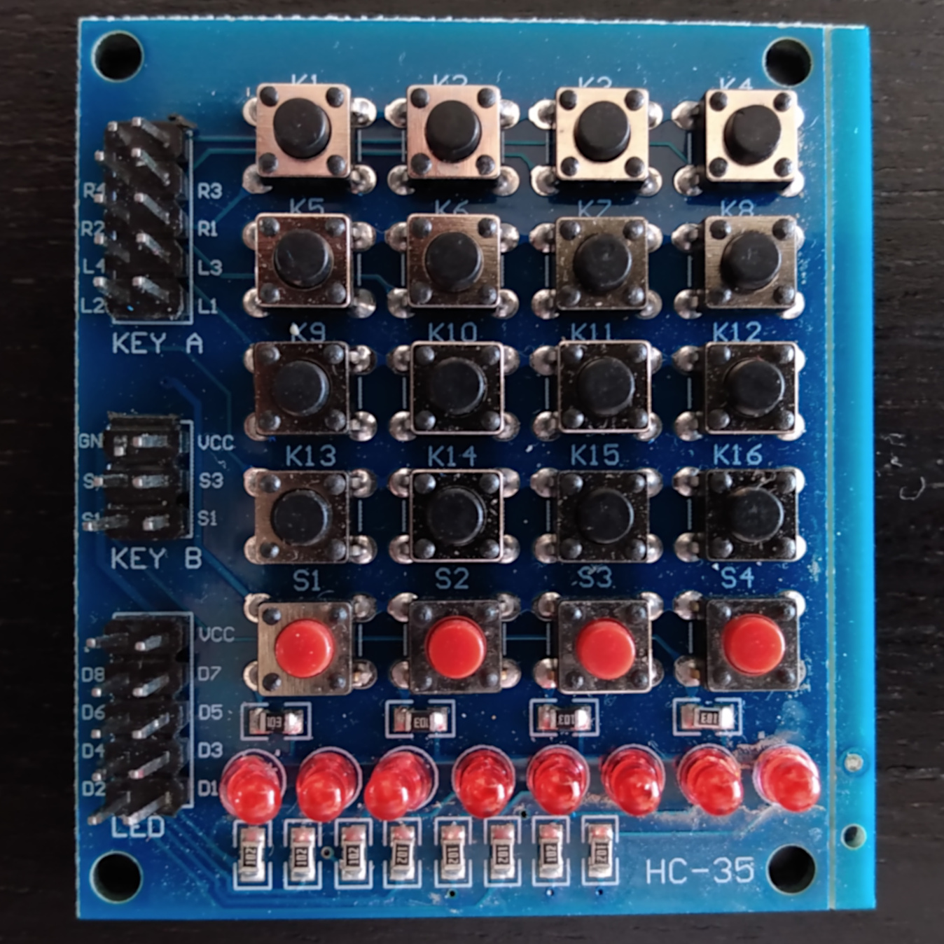
Documentation or not, the task seemed simple to me: There are three banks of pins on the left side of the board. The bottom bank is for manipulating the LEDs, and the two banks above that are for reading the state of the red buttons and the state of the black buttons, respectively. Eight LEDs, eight bits in a byte, not a huge leap to assume that each LED maps to a bit in a byte. It is not really clear whether the LEDs are ordered MSB first or LSB first. I am not good at reading board traces.
So, we need to have eight wires to drive the LEDs. VCC is clearly marked, but I didn’t know whether the board needed 5V or 3.3V. In fact, at first I guessed wrong and tried 5V. It doesn’t seem to have harmed the board, but after the fact, I thought maybe it would have been better to try the lower voltage first :-)
The ATtiny85 has 8 pins in total. We need a further four wires to read the state of the KEY B bank consisting of the red buttons, and we need an additional eight wires to read state of the KEY A bank consisting of the 4x4 keypad. Note the pins on the KEY A bank are labeled Li and Ri where I would expect L to stand for “line” and R to stand for “row” which seem like the same thing to me. I decided to anchor on “R is row” and “L is column” as a working assumption, and focus solely on getting some lights to blink first.
Before going further, I should note that by the time I got around the thinking about this, a couple of months had gone by. Luckily, I had picked some other bits and pieces I thought might come in handy if I ever got around to trying this. Here is a list of what I ended up using:
- A ten-pack of ATtiny85 chips
- Belker 45W 5V 6V 7.5V 9V 12V 13.5V 15V Universal AC DC Power Supply
- REXQualis Electronics Component Fun Kit
- Breadboard
- Jumper wires
- Extra LEDs
- Power supply module
- 74HC595
- Tiny AVR programmer
Note that stuff you find on Amazon tends to have a markup compared to the unit prices you find when shopping at speciality or overseas suppliers. And, prices on Amazon tend to vary a lot. I was not in a rush, did not have a specific project in mind, and just grabbed a thing or two when I thought the price was right. The Belker adapter is great. I have, of course, a box of wall warts accumulated over time, but with those either the specs turn out not to be what you want (if you can read them) or the tips don’t match etc. Since I bought this, it’s already been useful in multiple other contexts.
Well, I figured the first task was to actually be able to get something on the ATtiny85 to execute. I knew that I needed to install some drivers for the “programmer”, stick the chip in the right way (here’s where the 10-pack comes in handy: If you insert the chip in the wrong way, it burns because you end up swapping VCC and GND and 5V runs through going the wrong way … don’t trust your eyes, triple check before plugging the programmer in to your computer’s USB port). The datasheet has the pin out diagram as well as other good information:
![[ ATtiny85 8 pin DIP package pinout diagram ]](attiny85-8pin-dip.png "ATtiny85 8 pin DIP package pinout diagram")
I followed SparkFun’s Tiny AVR programming hookup guide followed by Drawing On An OLED With An ATtiny85 to produce some output on a 128x32 OLED screen to get warmed up.
The next task was to figure out how to drive the LEDs which require 8 wires using the five pins I had at my disposal. So, I started by staring at the contents of the “Fun Kit”. There are only two ICs included in the pack. I did not know what the 4N35 was for (it turned out to be an light sensor optocoupler) but it has only six pins, so clearly it could not do anything with mapping one bit at a time (aka serial) output to eight bits at a time (parallel). So, I searched the web for the only other IC in the package, 74HC595. TI’s page for the product mentions “8-bit shift registers with 3-state output registers” right under the product name. To be honest, that didn’t mean any thing to me and I almost navigated away from the page, but scrolling down a little (is it me, or is everything on the web in huge and huger fonts now?) revealed the description:
The SNx4HC595 devices contain an 8-bit, serial-in, parallel-out shift register that feeds an 8-bit D-type storage register. The storage register has parallel 3-state outputs. Separate clocks are provided for both the shift and storage register. The shift register has a direct overriding clear (SRCLR) input, serial (SER) input, and serial outputs for cascading. When the output-enable (OE) input is high, the outputs are in the high-impedance state.
Yay! It looks like the “fun kit” includes just the part I needed for this! Good.
Time to learn what the gobbledygook means … It sounds like it’s saying it takes serial input, puts bits in eight bins, and, when you give it the all clear, it puts those zeros and ones on some IO pins. Here is the pin-out:
![[ SN74HC595 pin out diagram ]](SN74HC595-pins.png)
QA - QH are the eight output pins. VCC is VCC, GND is GND. SER better be serial. O̅E̅ is “output enable” meaning put “put the bits you buffered on the pins”. QH′ seems to provide the same output serially.
OK, so I need to connect QA - QH to the LED inputs … I think I did this the “wrong” way by connecting QA to D1 on the keypad, but at this stage, I didn’t care what lit up … just that something did.
The big question is what to do with the five other pins. How do I drive them from the ATtiny85? I was confronted with a choice: I could read the datasheet, draw on my “vast” knowledge from electronics all gained in 8th grade, and translate the information in the datasheet to a program. Or, I could see if anyone else had done something similar. Searching for 74HC595 and Arduino led me to the documentation for the shiftout function:
Shifts out a byte of data one bit at a time. Starts from either the most (i.e. the leftmost) or least (rightmost) significant bit. Each bit is written in turn to a data pin, after which a clock pin is pulsed (taken high, then low) to indicate that the bit is available.
Nice. It turns out Arduino documentation is really good like Perl documentation (docs on both focus on giving you the information you need to be able to use a specific piece of functionality – For a contrast, see Python’s documentation which tends to obscure the information you need in dense prose). The docs for shiftout came with a complete example as well as a link to a tutorial on controlling the 74HC595 shift register. Of course, the mnemonics used in the pin-out diagram in the tutorial do not fully match the datasheet, but it is really nice to have these resources when you are trying to take the baby steps. It is easier to understand how you ended up blinking those if you can get them to blink in the first place.
Obviously, the tutorial is great. Explains all you need to know really. It is geared towards an Arduino board and those tend to have way more available pins than the ATtiny85. Laying cable on a breadboard is not my strong suit (never touched a soldering iron either), but after spending a moment considering my options, I decided to use the three available pins on the right side of the ATtiny85 (PB0 … PB2) for interfacing with the 595. While reading the tutorial, I noticed this:
“3 states” refers to the fact that you can set the output pins as either high, low or “high impedance.” … Neither example takes advantage of this feature and you won’t usually need to worry about getting a chip that has it.
Good. One less thing to worry about.
Anyway, I used whatever wires were available within the routing constraints and came up with this wiring:
![[ ATtiny85 SN74HC595 Liyafy HC-35 keypad breadboard wiring ]](attiny85-SN74HC595-HC-35-breadboard.jpg "ATtiny85 SN74HC595 Liyafy HC-35 keypad breadboard wiring")
The colors of the wires were dictated by available lengths because I did not feel like cutting and trimming or trying to lay out everything so that colors could be consistent. Right is mostly for communication between the 595 and the ATtiny85 and the left side is mostly for communicating with the LEDs. The power adapter is putting 5V on the left rails. The right rails are off. After discovering that the LEDs did not work with the 5V current, the power adapter proved to be really useful by letting me tap into a separate 3.3V fed by the same power source. Nice.
Note that the “fun pack” also included an active buzzer which is what helped me discover that the output pins on the 595 really were sending some signals by just plugging in to the bread board for each of them. It also helped me reassure myself that the ATtiny85 was at least doing something on those PINs. Not the most sophisticated debugging technique, but, then, printf debugging tends to be the quickest way to pinpoint problem code. The buzzer had a sticker that said “remove after washing”. I did not know if that meant the component had to be washed, but thanks to this answer on Electronics SE, I realized I could leave it on if only for the muting effect.
You may notice the extra RGB LEDs plugged in to the board (no resistors – that must be violating a cardinal rule somewhere). I mean, if I am going to flash lights, why not flash some more lights?
Here is the detail of the connections between the ATtiny85 and the 595:
![[ ATtiny85 SN74HC595 Liyafy HC-35 keypad breadboard wiring ]](attiny85-SN74HC595-HC-35-breadboard-detail.jpg "ATtiny85 SN74HC595 Liyafy HC-35 keypad breadboard wiring")
And, here is the code I used (basically just fiddled with the sample code until it looked pleasing to my eye):
// Adapted sample code in https://www.arduino.cc/en/Tutorial/Foundations/ShiftOut
// Code sample 1: Hello World https://www.arduino.cc/en/Tutorial/ShftOut11

// ATtiny85    SN74HC595
// ----------------------
// PB0 (5) <-> RCLCK (12)
// PB1 (6) <-> SRCLK (11)
// PB2 (7) <-> SER (14)

// ATtiny85
// --------
// 5V  <-> VCC(8)
// GND <-> GND(4)

// SN74HC595
// ---------
// GND <-> GND (8)
// GND <-> SRCLR (10)
//

// PB0 (5) <-> RCLK (12) ST_CP / latch / Storage register clock pin in tutorial
int rclk_out = 0;
// PB1 (6) <-> SRCLK (11) SH_CP / Shift register clock pin in tutorial
 int srclk_out = 1;
// PB2 (7) <-> SER (14) DS / Serial data input in tutorial
int ser_out = 2;

void setup() {
  pinMode(rclk_out, OUTPUT);
  pinMode(srclk_out, OUTPUT);
  pinMode(ser_out, OUTPUT);
}

void led_out(int b) {
  digitalWrite(rclk_out, LOW); // so LEDs don't change while the bits are being transmitted
  shiftOut(ser_out, srclk_out, LSBFIRST, b); // send the data
  digitalWrite(rclk_out, HIGH); // make the new eight bits available
}

void one_at_a_time() {
  for (int i = 0; i < 7; ++i) {
    led_out(1 << i);
    delay(500);
  }
}

void all_combos() {
  for (int i = 0; i < 256; ++i) {
    led_out(i);
    delay(500);
  }
}

void blink_all() {
  for (int i = 0; i < 100; ++i) {
    led_out(0);
    delay(250);
    led_out(255);
    delay(250);
  }
}

void loop() {
  one_at_a_time();
  delay(1000);
  all_combos();
  delay(1000);
  blink_all();
  delay(1000);
}
It is not visible in the pictures, but running this code revealed that I probably miswired the 595 outputs to the LEDs. I expected the one_at_a_time to basically walk from one side to the other regardless of wiring, but it really doesn’t look like that’s happening.
For now, I got my blinking lights. If I tap PB2 with the buzzer, I get a nice rythmic pulse.
Clearly, the next steps are to figure out how to correctly map the output pins of the 595 to the invidiual leds. There is also the issue of getting some input from the board. Iigure with the two open pins on the left side of this ATtiny, I have one more pin than I need to receive serial data. So, reading the read buttons seems to be a straightforward proposition: Just use a separate ATtiny85 to read the for pins, and send the output to the one that controls the LEDs. That way, I can also more easily debug the wiring. Press a button, see if I can toggle a specific LED.
I can also handle the keypad using one ATtiny85 for the rows and another for the columns. Row reader reads from column reader and then sends to ATtiny85 on the remaining pin. Itlooks like SoftwareSerial can help here. Combining row, column, and red button information into a single value seems to require nine bits six bitsfor daisy-chaining these.
Of course, there are also parallel to serial shift registers, but apparently they are not regularly included in “fun packs”. So, the question whether the challenge of daisy chaining three ATtiny85 to give the LED controller full key state information or whether it is better to locate a cousin of the 595 such as the 74HC165, but one of those is still not enought to read both sets of key states. Another alternative is the 74F676 which is a 16-bit Serial/Parallel-In Serial Out shift register. But 16-bit shift registers in DIP packages seem to be a rarity.
We’ll see what strikes me as more fun when get another couple of hours to try something. In the meantime, here is a short video of some flashing lights
You can discuss this post on r/attiny and HackerNews.
Note: Hope you enjoyed reading this post. Please note that I tend not to be too careful playing with electronics. Heck, I burned a poor litte ATtiny85 to a crisp when I plugged in the AVR programmer for the first time. It is definitely possible to fry various components (from the cheap ATtiny85 to your expensive computer) when working with things that carry a current and might end up short-circuiting. Further, you can really do a lot of damage if you interface with anything connected to AC. So, please be careful. While I am sharing this information for fun and informational purposes, it is your responsibility to take precautions and work in a safe manner.