This post is third in a series where I try to figure out how to use the three main functional components on the Liyafy HC-35 using an ATtiny85. In the first part, I discovered how to drive the LEDs with the ATtiny85 driving them using a 74HC595 serial to parallel shift register. That allowed me to dedicate three pins on the ATtiny85 to turn eight LEDs on/off independently. More importantly, it still left me with two open pins on that chip which I can use to receive information about the state of the two sets of keys on the HC-35.
In the second part, I verified that I could simply read the pins for the four red keys on the HC-35 and have a pin free to transmit key state out. That was almost trivial.
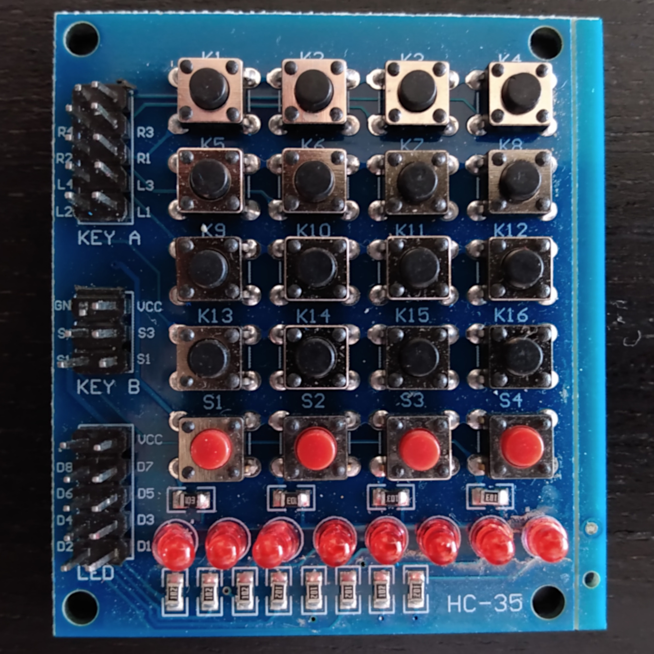
Those experiments gave me the confidence to proceed with the assumption that I could simply read the row and column pins and figure out which key was pressed. I was wrong. In retrospect, I should have known from the lack of resistors for the black keys that they were not going to work like the red keys. Here is a picture of the HC-35 so you can see what I am referring to:
Recall that the ATtiny85 has five pins which can be used for input-output. Emboldened the naive assumption that the black keys worked just like the red ones did, I proceeded to fish out a 74HC165 parallel to serial shift register, connect all the row/column pins on the HC-35 to the input pins on the 165, wire up the signals between the ATtiny85 and wrote a short sketch to show everything worked.
Except, it didn’t.
That’s when I noticed the lack of resistors for the 4x4 keypad. At first, I thought it was a cost saving measure, so I put some 10K resistors between the row/column pins and the inputs to the 165 … Hmmm.
That didn’t work.
I did some searching and found the [scanning routine] in Keypad.
It assumes that you have eight pins to dedicate, so it is not useful to me in that regard, but I finally understood how the 4x4 keyboard state is supposed to be read. I should note that I am writing this as I discover, so the current working theory might also be wrong, but, as I understand this, the 4x4 keypad does not use the power from the 3.3V input that the LEDs and the red keys use. Instead, when you want to read the state of the keyboard, you set the column pins to HIGH one by one, and read the row pins. If a button is pressed, that row will read LOW. That’s how you know which key is pressed.
There doesn’t seem to be a way the 165 is going to be sufficient for this:

Those parallel input pins don’t change direction.
After some research, I realized what I really need seems to be a 74HC4051N 8-bit multiplexer/demultiplexer. It seems like I need three pins on the ATtiny85 to tell it to select which pin to read from/write to and one more pin to actually read/write. I am operating under the assumption that I can just wire the enable pin to GND. That means I need one more pin which I can use to communicate the key state with the outside world. Without that pin, there is no point to this. This is pure speculation though. I do not have the 4051N in hand yet. Here is the description from the datasheet for reference:
74HCT4051 is a single-pole octal-throw analog switch (SP8T) suitable for use in analog or digital 8:1 multiplexer/demultiplexer applications. The switch featuresthree digital select inputs (
S0,S1andS2), eight independent inputs/outputs (Yn), acommon input/output (Z) and a digital enable input (E). WhenEisHIGH, the switches are turned off.
I would still like to test if I understood how to read the state of the 4x4 keypad correctly. To that end, I am going to use another 595. It is going to be used to set the columns to HIGH. When looking at each column, we’ll also a set an LED corresponding to the column. I’ll use the left-most LEDs to indicate which column is being set to HIGH (i.e. being prepared to be read from). I am going to wire the row pins to the LED right hand side LED pins so that the pin corresponding to the row will turn off when the key at the intersection of the row/column is pressed. Not very practical, but, at least it will verify that I understood how this thing works.
For a recap of the wiring between the 595 and the ATtiny85, please refer to the “Fun with an ATTiny85, Liyafy HC-35 keypad with eight LEDs, and a serial to parallel shift register”.